Blog

What Is a Horizontal Machining Center and How Does It Work?

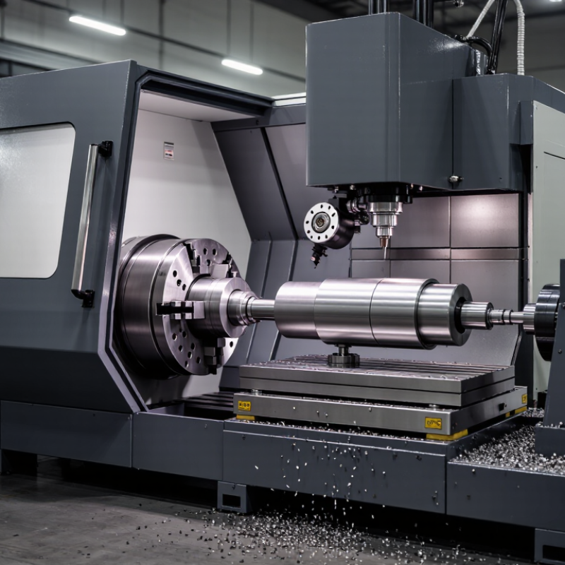
A horizontal machining center is more than a CNC machine with a sideways spindle. It is a coordinated manufacturing system built for accuracy, access, and repeatable production. Its spindle faces horizontally, while a pallet usually holds the workpiece. This arrangement lets chips fall away from the cutting zone instead of collecting around the tool. It can also expose several sides of a component with fewer setups.

Professor Yusuf Altintas, a leading machining researcher and author of Manufacturing Automation, writes, “Machining is a complex process involving a large number of variables.” That observation explains why a horizontal machining center requires more than basic programming knowledge. Tool length, workholding, coolant pressure, spindle speed, cutting forces, and thermal growth can all influence the final part. Small errors become visible on a machined bore or a tight-tolerance mounting surface.

In practice, the machine rotates the tool and moves the workpiece along controlled axes. Many models include a rotary table, automatic tool changer, and pallet changer. These features reduce idle time and support unattended production. The details bite.

A skilled operator still checks tool wear, fixture rigidity, and chip evacuation. Automation does not remove judgment. It changes where judgment is needed. The machine may complete a cycle perfectly, yet the process can remain poorly designed. That is an uncomfortable point. Understanding how a horizontal machining center works means examining both its impressive capabilities and its practical limitations.
What Is a Horizontal Machining Center and How Does It Work?

Definition and Core Structure of a Horizontal Machining Center

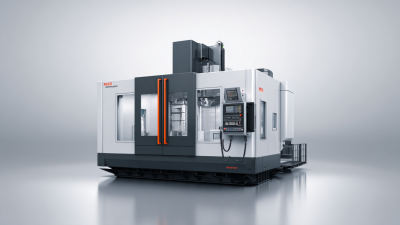
A horizontal machining center (HMC) is a computer-controlled machine tool with its spindle positioned parallel to the shop floor. This orientation defines its core structure. A rigid column supports the spindle head, while a worktable carries a pallet or tombstone fixture. The tombstone holds several workpieces vertically. An automatic tool changer stores cutting tools beside the spindle. Enclosures contain coolant and chips.

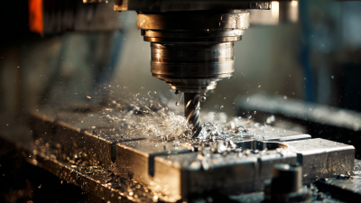
During operation, the spindle approaches the workpiece from the side. The table moves along controlled linear axes, while rotary motion may index the pallet between faces. A typical cycle can mill, drill, tap, and bore several surfaces without removing the part. This reduces repeated setup errors. It also improves access to deep cavities. Chips usually fall away from the cutting zone, although poor coolant flow can still cause recutting.

Fortune Business Insights reported that the global CNC machine market reached about 86.83 billion dollars in 2023. Its forecast suggests continued growth through 2032, driven partly by automated production. The figure covers many CNC types, not HMCs alone. That distinction matters. In a real shop, an HMC’s value depends on spindle power, pallet capacity, positioning accuracy, and fixture design. A heavy tombstone can improve productivity, but it may reduce usable travel. The design looks efficient. The trade-offs are not.

How the Machine Coordinates Its Cutting Movements

What Is a Horizontal Machining Center and How Does It Work?

A horizontal machining center cuts with its spindle parallel to the shop floor. Its table usually moves along the X and Z axes, while the column or spindle travels along Y. A rotary pallet can add a fourth axis. Together, these movements position the workpiece under the cutting tool. The controller reads programmed coordinates, then synchronizes feed rate, spindle speed, and tool compensation. Linear interpolation creates straight cuts. Circular interpolation forms bores and curved pockets. The result feels simple at the operator’s panel, but accuracy depends on many small corrections.

A probing cycle checks the workpiece origin before cutting. Encoders report actual axis positions, often within microns on well-maintained equipment. ISO 230-2 provides the standard method for testing positioning accuracy and repeatability. The 2023 Gardner Intelligence World Machine Tool Survey valued global machine-tool consumption at more than 80 billion U.S. dollars. That scale explains the pressure for faster, repeatable coordination. Still, a perfect digital path does not guarantee a perfect part. Heat, tool wear, vibration, and a slightly dirty pallet can shift the result.

Tips: Keep the work offset close to the actual datum. Measure the first part, not just the screen values. Review tool wear after deep pockets or long cuts. The U.S. Department of Energy reports that industrial motor systems can represent a major share of plant electricity use, so unnecessary rapid movements also deserve attention. A shorter toolpath may improve both cycle time and energy use. Sometimes, slower is safer.

Workpiece Setup and Automatic Tool Selection

A horizontal machining center places the spindle sideways, allowing chips to fall away from the cutting zone. Workpiece setup still determines accuracy. On the shop floor, operators mount the part on a pallet, clean every contact surface, and verify the fixture datum. A single chip under a locator can shift the part noticeably. Small errors multiply.

The control then uses probing cycles to find the work offset and confirm the part’s position. For repeat jobs, automatic pallet changing can reduce handling variation. According to the International Federation of Robotics’ World Robotics 2024 report, 541,302 industrial robots were installed worldwide in 2023. That growth reflects a wider move toward connected, repeatable production, but automation cannot correct a poorly seated workpiece.

Automatic tool selection begins with the machining program. The control reads each tool number, checks its offset, and calls the tool changer before cutting. Tool length, diameter, material, and remaining life must match the programmed operation. A worn drill may still pass a basic presence check. It can also produce an oversized hole. Tool-life monitoring helps, though sensor readings are not always perfect. Deloitte’s 2024 Smart Manufacturing survey found that 86% of surveyed leaders viewed smart manufacturing as important for future competitiveness. In practice, that means linking tool data with inspection results, rather than trusting the magazine alone. A careful operator still checks the first component, watches chip color, and questions unexpected load changes.

What Is a Horizontal Machining Center and How Does It Work? - Workpiece Setup and Automatic Tool Selection

Process Dimension Typical Practice or Data How It Works in a Horizontal Machining Center Main Benefit
Machine orientation The spindle axis is horizontal, commonly parallel to the shop floor. The cutting tool approaches the workpiece from the side, while the workpiece is secured on a table or pallet. Improves access to multiple sides of a part and helps chips fall away from the cutting zone.
Workpiece loading Parts are loaded manually, with a crane, or through an automated pallet system, depending on part size and production volume. The operator places the workpiece or fixture on the pallet, aligns it with locating elements, and clamps it securely. Creates repeatable positioning and reduces setup variation between parts.
Fixture selection Common options include vises, modular fixtures, tombstones, angle plates, and custom hydraulic or pneumatic fixtures. The fixture supports the part while leaving sufficient clearance for the spindle, tool holder, and chip evacuation. Provides rigidity, access, and stable cutting conditions.
Locating method Locating pins, precision stops, datum surfaces, and pallet reference systems are commonly used. The locating system establishes the work coordinate relationship between the part and the machine axes. Supports dimensional consistency and faster reloading.
Clamping force Clamping must resist cutting forces without deforming thin walls or finished surfaces. The operator applies force through mechanical, hydraulic, or pneumatic clamps at structurally strong areas of the workpiece. Prevents movement, vibration, and workholding-related dimensional errors.
Datum setting A work coordinate system is established from defined part datums, such as a face, bore, or precision edge. A touch probe, edge finder, probing cycle, or manual measurement determines the part’s position and orientation. Reduces manual calculation and improves setup accuracy.
Pallet exchange Many horizontal machining centers use one pallet in the machining zone while another is loaded outside the enclosure. A pallet changer transfers the prepared workpiece into the machine after the previous cycle is complete. Allows workholding and part loading to occur during machining, reducing non-cutting time.
Typical machining envelope Small and medium horizontal machines often provide approximately 500–1,000 mm of X-axis travel and 500–900 mm of Y-axis travel; exact capacity varies by machine configuration. The control limits programmed motion to the available travel and workholding clearance. Helps determine whether a part can be machined in one setup or requires repositioning.
Automatic tool storage Tool magazines commonly hold about 20–60 tools on general-purpose machines; larger production systems may hold more. Each tool is assigned a magazine pocket, tool number, length offset, diameter data, and permitted machining operations. Makes multiple operations possible without stopping for manual tool changes.
Automatic tool selection The CNC program calls a tool by its assigned tool number, while the control verifies tool data and change conditions. The automatic tool changer removes the current tool, retrieves the programmed tool from the magazine, and places it in the spindle. Reduces operator intervention and maintains a repeatable operation sequence.
Tool selection criteria Selection is based on material, feature geometry, required tolerance, surface finish, cutting depth, and available spindle speed. Programming software or the machinist assigns tools such as face mills, end mills, drills, reamers, taps, or boring tools to individual operations. Matches tool capability to the cutting task and helps control tool wear.
Tool length and diameter offsets Offsets are measured with a presetter, tool probe, or manual measurement method before production machining. The CNC control uses the stored values to position the tool tip and compensate for tool geometry. Improves positional accuracy and prevents incorrect tool-tip location.
Cutting parameter control Spindle speed, feed rate, axial depth of cut, and radial width of cut are adjusted for the workpiece material and tool diameter. The CNC program commands the spindle and axes while coolant or air assists with heat and chip control. Balances productivity, tool life, surface quality, and machine load.
Multi-face machining A rotary table or indexed pallet can present different faces of the workpiece to the horizontal spindle. The machine rotates or indexes the workpiece so several sides can be drilled, milled, bored, or tapped in one setup. Reduces repositioning errors and can shorten total production time.
Chip evacuation Gravity-assisted chip drop, coolant flow, air blast, and chip conveyors are frequently used. The horizontal spindle orientation allows chips to leave vertical walls and deep cavities more readily than in many vertical setups. Reduces chip recutting, heat buildup, and possible surface damage.
In-process verification Probe checks, tool-break detection, first-piece inspection, and periodic dimensional measurement are common practices. The control or operator compares measured results with programmed offsets and adjusts the process when necessary. Detects setup drift, tool wear, and dimensional deviations before a large batch is completed.

Step-by-Step Horizontal Machining Process

A horizontal machining center cuts with its spindle parallel to the floor.

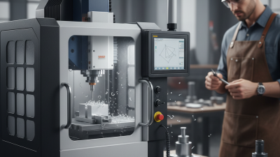
The step-by-step process begins before the first tool turns. The operator loads a workpiece onto a pallet and secures it in a rigid fixture. Datum surfaces are cleaned, then probed or touched off. This prevents a small setup error from becoming a large positional error.

Not a minor detail. The pallet must sit fully against its locating points.

The control calls the first tool, checks its offset, and starts roughing passes. The horizontal spindle approaches the part from the side. Rotary tables can expose several faces without removing the workpiece. This reduces repeated alignment and improves feature-to-feature accuracy. Coolant carries heat away, while gravity helps chips fall from the cutting zone.

Chips still matter. Deep pockets require deliberate flushing, or chips may recut and damage the surface.

During machining, probing can verify hole locations, stock, and tool wear. Operators should review those readings rather than trust them blindly.

Finishing passes use lighter cuts and controlled feeds. A final tool may produce bores, threads, or angled surfaces. Inspection follows with gauges or a coordinate measuring machine.

The International Energy Agency’s Energy Efficiency 2024 report identifies motor-driven systems as major electricity users, often cited at about 53% globally. The U.S. Department of Energy also reports that motor-driven equipment consumes more than half of industrial electricity. Spindle load, coolant pumps, and idle time therefore deserve measurement.

Cutting faster is not automatically better. Measure it.

Common Applications and Key Operational Advantages

A horizontal machining center positions its spindle parallel to the shop floor. The spindle approaches the workpiece from the side, while a rotary table can present several faces for cutting. This arrangement supports drilling, milling, tapping, and boring in one controlled setup. Chips often fall away from the cutting area instead of collecting around deep pockets. Chip control matters.

These machines suit engine parts, pump housings, transmission cases, and large structural components. Automotive production uses them for repeated aluminum and steel parts. Aerospace suppliers may machine complex housings with strict dimensional requirements. Toolmakers also use horizontal centers for parts requiring accurate work on multiple sides. With pallet changing, one fixture can load while another part is being cut. This reduces idle spindle time during steady production.

The main operational advantage is fewer reclamping operations. Fewer setups can reduce alignment errors and protect positional accuracy between features. Better tool access can also improve surface quality inside deep cavities. In practical production, cycle time depends on fixture design, tool selection, and operator judgment. Setup still matters. A worn tool can cancel the benefits of an advanced machine. Coolant flow, chip evacuation, and workholding require regular checks. From a shop-floor perspective, horizontal machining is powerful, but not automatic. Some parts gain little from it when their geometry is simple.

↑